The Edit Part dialog box is the main means of editing the section shapes, dimensions and creating the
nodes of a part. The dialog is opened either at:
1. Initial part creation
2. Using the 'Edit Part' command with a single part selected (otherwise the command is disabled).
3. Double clicking on a part in the CAD view.
The edit part dialog box opens on the Part tab CAD view showing the selected part, on its own, in a 3D
CAD view. The direction of the view can be switched to any of the four standard views from the 'View'
menu of the dialog
Edit Part Dialog Overview
The dialog consist of four main area plus a local menu.
Part section selector: - At the top of the dialog is the part section selector, used for selecting the section
of the part and one or both ends.
Fig: Part Section Selector
Command dialog - Below the part section selector is the local command dialog. This is similar to the command dialog of the main cad view and its
content (i.e. the visible controls) depend on which tab is
selected in the CAD views.
Dimension editor - Below the command dialog panel and to the left is the dimension editor. The
dimension editor displays any dimensions accompanying the currently selected CAD view and makes these
dimensions available for editing (see: Using the Property Editor ).
CAD views - The CAD views section is the largest area of the edit part dialog. It has several CAD views
showing different aspects of the part. There are four such views placed on four tab pages. These are the
'Part', 'Section', 'Nodes' and 'General' tab pages (discussed below). The currently selected page
determines what controls are visible in the local command dialog and what dimensions appear in the
dimension editor.
Match Selection - The match settings appear a the base of the edit part dialog. These settings define the
type of matching to initiate one the part editing is complete and the dialog closed.
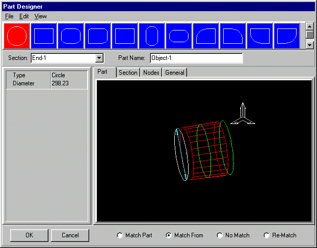
The Part Tab Page
The Part tab page shows the part with section shapes displayed offset from the ends and at the mid center
line point of the part. One of the sections is highlighted as the current selection. The others are colored
green to indicate they are available for selected.
Fig: Edit Dialog Part Tab
The section shape of the part can be altered by selecting one of the sections in the 'Part section selector'
at the top of the screen. The chosen section is automatically applied to the currently selected section of
the part. If an end section of the part if selected then just that end is the part is changed to adopt the new
section. If the mid section of the part is selected then both ends adopt the new section shape. the chnge is
immediately visible in the Part tab CAD view.
The dimensions of the currently selected part section are displayed in the dimension editor. Any of these
dimensions can be altered as required (see: Using the property editor ).
Altering any of the section
dimensions becomes immediately visible in the CAD view and the part is automatically adjusted. If the
currently selected section is the mid section of the part then both ends are altered to this section with the
same dimensions values at each end.
To edit the part to become an adapter part the procedure is to select each end section in turn, select a
section for the end from the Part section selector and type in the dimensions of the section.
The Section Tab Page
The Section tab page simply holds another view onto the selected section for convenience. It is a 2D direct
view that makes the view of the section much clearer. Altering the section dimensions from this view has
the same effect in the Parts tab as altering the dimensions with the Part tab current. Equally altering them
in the Parts tab alters them here also.
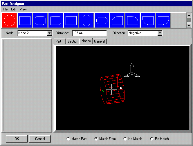
The Nodes Tab Page
The Nodes tab is provided for adding and deleting new nodes to the object. Nodes are used for linking
objects together and are important for assembling multi-object designs. Initially all parts are created with
a node at each end. The end nodes are permanent and cannot be deleted. Additional nodes along the
center line may be required for creating tee and junction connection (see: Connecting and Intersecting
Objects ).
The Nodes CAD view shows the 3D part with a cross cursor sliding along the object center line as the
mouse pointer is moved over the view. The cross cursor is moved to the nearest point to the mouse cursor
on the object center line. One of the nodes on the part is selected and shown as a small filled white circle,
this is the currently selected node. The other node/s are shown in hollow green (i.e. unselected but
available). The green indicates (as always) that the node is selectable. Selecting one of the green nodes
with the mouse replaces it as the currently selected node. The command dialog 'Node' combo box reflects
the change. Selection of the current node can also be made directly from the command dialog Node combo
box.
Fig: Edit Part Dialog - Nodes Tab Page
The 'Distance' edit box displays the current distance of the cross cursor from the currently selected node.
The 'Direction' combo box defines whether the displayed (or typed) distance is in a positive or negative
direction from the current node.
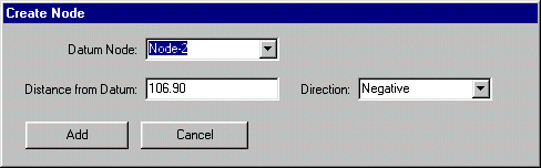
Creating a New Node - To create a new node any of the following actions invokes the 'Create Node'
dialog box:
1. Select the 'Edit|Create' node command in the menus
2. Right click the mouse and use the 'Create Node' command in the pop-up menu.
3. Simply select with the mouse whilst away from close proximity to any existing node (close proximity to
the node will simply select it as current).
Fig: Create Node Dialog box
Type the position of the new node, as a distance from the currently selected datum node, into the
'Distance from Datum' edit box. Select the 'Add' button to add the node and close the dialog. The new
node is created and becomes immediately visible in the Nodes tab page CAD view.
Deleting a Node - To delete a node first select it with the mouse then use either the right click pop-up
menu 'Delete Node' command or the dialog menu 'Edit|Delete Node' command. These commands are only
available if the currently selected node can be deleted. The end nodes of the part are permanant and
cannot be deleted.
The General Tab Page
The General tab page provides access to miscellaneous dimensions and values relating to the part. The
possible values are as follows:
1. Z-Angle: The Z-Angle is the rotation of the part from vertical. In the case of circular parts this appears
as the moving of the seam position which is by default at the most vertical position on the part section. In
the case of objects with flat sides the effect of rotating the object is visually obvious as it is altered.
2. Net-Angle: The net angle of the part defines the draft accuracy to which the part intersections and flat
patterns are calculated. It defines an increment around the 360 degrees of the object which act as
calculation lines. This value does affect the internal calculation of results but is not critical for output if the
Options dialog (see Options dialog DXF tab) 'Use Global Net Angle' option is checked (as it is by default). If
this option is checked then all output is recalculated to the accuracy of the Options dialog 'Global Net
Angle' edit field value before exporting.
Match Selection In the Edit Dialog
The Match selection appears at the base of the edit part dialog. This setting indicates the kind of matching
that should be initiated when the part editng is complete and the edit part dialog is closed. The possible
settings are:
1. Match Part (same as main window menu 'Match Selected' command). 2. Match From (same as main window menu 'Match From Selected' command). 3. No-Match 4. Re-Match (Same as main window menu 'Re-Match Design' command).
The act of editing the section shape or size of a part may mean that it is no longer matched to the parts to
which it is linked. If the match is invalid then the intersection may not be feasible. The matching
commands are designs to ensure that the connection that are made are valid.