The main view dimension editor is visible to the left of the main window. Its purpose is to display the
dimensions associated with the active CAD view. The dimension editor can be hidden if preferred - to leave
more room for the CAD views - but it can at any time be re-displayed using the 'View|Show Editor'
command. Dimension editors like the main property editor are used on occasions in other places, such as
the Edit Part dialog box. These editors all work in the same way, invariably accompanying a CAD view that
displays a visual response of altering dimensions values.
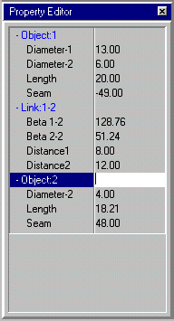
Fig: Property Editor
Displaying Properties
The properties displayed in the property editor are sometimes fixed (e.g. as for the Swept bend generator)
or in other cases they depend on the objects selected in the associated CAD view. In the case of the main
window property editor the properties that appear in the editor are the properties associated with the
selected objects in the active CAD view. Usually for CAD designs there are no such dimensions, but for
parametric designs there are always some. Each time the object selection set changes in the CAD view the
properties are updated.
Selecting a Property and/or Dimension
To edit a property click on it with the mouse to highlight it. Often a property in the editor has an
accompanying graphical counterpart dimension in the accompanying CAD view. If so the dimension is also
highlighted. It is also possible to do this in reverse and select a graphical dimension in the CAD view and
have the associated property automatically selected in the property editor.
In some cases the dimensions are grouped. Groups appear in the property editor with a small '+' or '-' to
the left of the group name ('+' if collapsed and '-' if expanded). To expand a group simply click on it. Or if
the group is already expanded clicking on it closes the group.
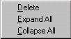
Fig: Property Editor Popup Menu
A right click on the property editor invokes a pop-up menu with the 'Expand All' and 'Collapse All'
commands. These commands can be used to automatically expand or collaspe all groups in the editor.
Generally the visibility of the dimensions associated with properties depends on the visiblity of the
property in the property editor. If a graphical dimension is selected that is in a property group that is
collapse (i.e. the property is not visible) then the group is automatically expanded to display the property
end select it for editing.
Editing a Property
To edit a property type in a value and press the enter key. If the typed value is invalid (e.g. non-numeric
characters where numeric input is required) then the program emits a beep and no alteration is made. If
the value is accepted the associated CAD view is updated to reflect the change. Other property values may
also change if the properties are mutally dependent in some way.
Command Dialog Interaction
The command dialog often has controls that work in unison
with the property editor. In fact in the case of
parametric designs the property editor can be hidden and all properties still edited via the command
dialog. Generally the selection of the properties is a little more inconvenient without the editor, although
the command dialog does also works together with the selection of graphical dimensions so the dialog can
be used effectively without the property editor for editing properties.
Parametric Design Property Groups
Parametric designs make use of property groups. Each object has a group of its own (named as the object
name) and each connection between two objects has a group (named 'Link-<object1_name>,<object2_name>). The individual object groups are visible in the property editor only
when the object is selected. The link groups are visible only when both objects involved in the link are
selected.