Connecting and Intersecting Objects
Previous Top Next

Creating an Intersection - Normally  to generate an intersection between two objects they must be connected together. Connections are created between objects by linking a node  on one object to a node on the other. By default an object has a node at each end of its center line but more nodes can be added along the center line of the object. The actual linking of the nodes is done using one of the snap tools during certain operations where an object is 'Active '.

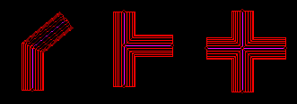
Connection types - The actual nodes selected on two objects to form a link are important in determining the type of intersection they have. If two end nodes are linked together the result is to form a '
Bend ' connection. If an end node on one object is linked to a mid-centerline node on another object then the first object will intersect the second as a 'Tee-On'. Equally if a mid-centerline node on the first object is linked to an end node on the second object then the second object will 'Tee-On' to the first. If a mid-centerline node on both objects are linked together then the intersection formed is a junction (or crossover).

Bends, Tees, Junctions
graphic
Fig: Bend, Tee and Junction Connection


Forming Connection

The design process for forming connections is fundamental to Sheet Lightning design. Connections can only be formed while an object is '
Active '. This means we must be either moving the whole object by dragging it with the mouse in response a 'Move', 'Duplicate', 'Paste' or 'Offset' command, or we must be moving one end of the object by dragging it with the mouse either at the initial creation of the part of in response to the 'Normal Activate' or 'Oblique Activate' command. In all of these cases the whole object, or one end of the object is in the process of being moved by dragging one of the object nodes in the 3D view. All of these commands prompt for a node to be selected to initiate the move, or in the case of initial object creation the dragged node automatically becomes the second end of the new object. A link is formed between the active object and a static object as the dragged node is dropped on another node using one of the 'Snap tools' (Note: a link is not formed by simply dropping a dragged node near another node. A snap tool must be used).

Snap Node graphic
  - The simplest snap tool is the 'Snap Node' tool. If 'Snap Node' is selected with an object active you are prompted to select a node on one of the static (inactive) objects. When this node is selected the dragged node is snapped to the position of the selected node. A further mouse click confirms the selection and the actve object is fixed at the new position and a connection is formed between the dragged node on the active object and the selected node on the static object. The connection should become evident when the next 'Weld All' or 'Weld Selected' command is executed.

Snap Center Line graphic
  - A slightly more complex way of selecting a node on a static object in order to form a connection is by using the 'Snap Center Line' tool. This snap tool can be used to either select an existing node on a static object, or for creating a new node on the static object and forming a link with it and the active object node. When the 'Snap Center Line' tool is selected you are prompted to select one of the static object center lines. On selection of the required center line the 3D cursor movement is snapped (i.e. restricted) to slide along the center line in the view. The next cursor click confirms the current cursor position on the center line to be the position to create a new node, or if a node already exists at the selected point then this node is used for the link. The active object is dropped at this point and the active object and selected object are connected via the dragged node and the new/selected node on the static part.

Other Snap Tools - All other snap tools affect only the orientation and current position of the active part and are not used in any way to form connections.