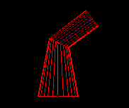
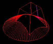
A Bend connection is formed between two objects when they are linked together by their end nodes. In
some cases a successful bend intersection also requires the section sizes of the two objects to be matched
so that the two objects fully terminate each other when they are intersected.
Fig: Valid bend intersection
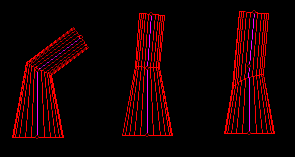
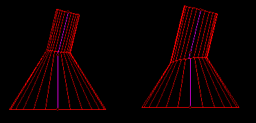
There are two distinct cases of bend intersection that can occur. These are (1) Crossing intersections and
(2) Inline intersections, as illustrated below. In the case of 'crossing' intersections it is usually essential to
have matched section sizes for the bend intersection to be successful. In the 'inline' cases the objects can
satisfactorily 'terminate' each other and form a successful intersection without the need for matching
(although some types of matching can still be advisable).
Fig: Bend intersections - Crossing, Inline matched, Inline unmatched.
Crossing Intersections
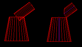
For crossing intersections, if the objects are not matched then their intersection will be interpreted as a tee
intersection instead of a bend, where the smaller object is teed on to the larger. Generally this is not a
valid intersection because the tee occurs so close to the end of the larger object, but in some cases where
multiple objects are joined by their end nodes it may be a valid design.
Fig: Invalid intersection (1.Outline 2.Cut)
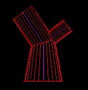
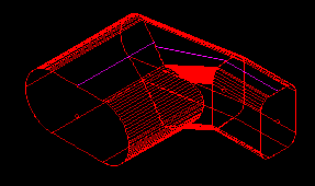
The following image shows the same intersection with a third object added. The additional object is
matched to the cone and therefore forms a valid bend intersection. The smaller cylinder can now be
matching into the bend correctly to form a valid 3-way bend connection with the cylinder unmatched. In
effect the cylinder is treated as a tee onto the two other parts together.
Fig: Bend intersection of 3 objects with an unmatched object
NOTE: to achieve a successful intersection in the above case it is necessary to adjust one of the more
complex 'Weld options'. In this case just the 'Termination Level' option is raised to '2nd'. Normally the
termination level is set to 'None' because most designs are fully matched and the termination checking for
fully matched objects is redundant. For large designs the termination setting can slow down the speed of
the intersection calculation so the default setting of 'None' is nothing more than a time saving measure.
For designs with few parts this is generally not a problem so the termination level can be raised for all
designs until the calculation speed becomes an issue.
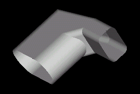
Inline Intersections
Inline bend intersections are in some ways much more flexible that crossing intersections because the
objects fully terminate each other irrespective of their section sizes. This applies to all section shapes (see
example below). Note that inline does not necessarily mean that the object center lines are lined up. There
may be some difference in their orientation but the taper (or flare) of the objects may still mean that they
are an inline case. Often by reducing the taper of one of the objects the intersection changes from an
inline case to crossing case.
Fig: Inline intersection - cone to rectangle.
There are one or two special considerations to make for inline object intersections which may still mean
that it is preferable to perform some kind of section size matching of the objects. First of all the most
common inline intersection is where the center lines are exactly aligned. Often in these cases the the
section shapes of the objects at their ajoining ends are the same. In these cases there is a common
requirement to simply match the two faces to be the same size and shape. This is called face matching.
Secondly in the case of inline circular object intersections (cones and cylinders) it may be desireable to
match the objects. The advantage is that the intersection gives a straight cut when viewed from the side,
whereas if the objects remain unmatched the side view of the intersection appears curved.
Fig: Bend circular - matched straight, unmatched curved.
In the case of circular matching sections the objects are not 'face matched' to achieve the straight cut,
they are matched using something called the 'common central sphere' (CCS - only applicable for circular
sections). This can be overridden and face matching used instead but the face match may product the
curved line. Also the CCS match has a great advantage that any number of circular sectioned objects
(cones and cylinders) can be intersected at the same point and each mutually terminates all the other. Ths
means 1. all cut lines are straight and 2. there is no need to raise the complex options such as the
'termination level' option (discussed above) to achieve a successful intersection.
Complex Bends
Finally Sheet Lightning s capable the most complex bend intersection. The matching facilities work for all
sections enabling objects of entirely different shape to successfully terminate each other in the bend.