The Angle Snap tool is one of several Snap Tools . Its purpose is to
snap the orientation of the currently active object to a particular relative angle to the center
line of one of its linked objects (or construction
lines) in the currently active plane. The angle snap command becomes available whenever the current
prompt is for the selection of a 3D point and an object is active in the 3D CAD designer.
When the angle snap command is selected a dialog pops up prompting for an angle. Having entered the
angle the CAD designer highlights all eligible linked objects with which the currently active part can align
and highlights then (colored green) prompting for a selection. This occurs even if there is only one possible
object with which the active object can be oriented. An object selection must be made with the mouse or
via the command dialog for the command to proceed and point selection resumed.
An object is selected by moving the mouse pointer close to a highlighted object and pressing to select it. If
none of the highlighted nodes are close to the selected point then the system issue a Beep and part
selection continues.
The object and point selection process can be aborted at any time using the escape key (ESC).
Once a part is successfully selected it is indicated by the special highligh (colored cyan - or light blue). Any
other eligible linked object continue to be displayed highlighted green which shows that an object
reselection can be made at any time by moving the mpouse pointer within selection proximity and
selecting.
After object selection the CAD designer prompt continues with the point selection. However the movement
of the cross cursor (representing the current actual 3D cursor point) is now dynamically restricted to the
relative angle alignment with the selected part. Also an angular dimension alignment indicator shows the
current alignment of the active part. The next mouse button press selects the point.
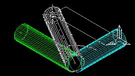
Fig: Relative Angle Snap - Dynamic Alignment
The dynamic alignment of the active object to the relative angle to the selected part, during mouse
movement, after part selection, can have as many as 4 possible alignments in the current active plane. In
other words an angle of 60 degree for example cou;ld be aligned in the active plane to two different angles
on each side of the selected part. The dynamic alignment always aligns to the nearest angle to the mouse
pointer, so the mouse must be moved close to the required position for the point selection to be made.
The Angle Snap Dialog
The angle snap dialog replaces the point selection dialog when the angle snap command is selected. The
dialog appears on the usual command dialog panel just above
the 3D CAD view. Note that on the left of
the dialog is a scroll bar. This indicates that on this occasion the dialog has more than one page.
Fig: Snap Angle Dialog - Page 1
Fig: Snap Angle Dialog - Page 2
These snap relative angle dialog edit fields are identical to the dialog edit fields of the normal point
selection dialog for an active part (see: ???), except for the addition of two extra edit fields (see below)
and the direct point input becomes read only (because point selection is now restricted to the angular
orientation). The dialog continues to offer object length locking as with unrestrained point selection for an active object .
Angle: - The angle field defines the angle to which the active part is dynamically snapping during mouse
movement. This is the angle that was input at the angle dialog prompt. It can be altered at any time
during the process.
Relative Object: - The relative object is the selected part to which the dynamic angle snapping is
occuring during mouse movement. This is the part selected immediately after selecting the angle snap tool
and inputting the angle. The relative object can be reselected at any time with either the mouse or the
Relative Object combo box.
Section of the Point
The final point selection is made by a further press of the mouse button. If the length have been
fixed/locked the cross cursor will at this point be pinned to a location, waiting for final point selection
confirmation.