- What is "Matching"
When two objects are related in the form of a tee, bend or junction then a "matching" operation can be performed. The operation of matching involves automatically altering the dimensions of an object to fit the dimensions of a related object in a particular manner. The various matching commands available are accessed through the "Match" pull-down menu or through the match commands in the design menu.
- Pipe Bends
To illustrate a simple case where matching may be required, consider a pipe bend relationship. If two objects are related together as a bend, then they must be of such a size to ensure that they cut each other off completely when put through a cut and weld operation. If, for example, the two objects are pipes (or cylinders), it would be impossible to produce a bend where the pipes were of different diameters. They would no doubt intersect each other but they would not properly cut each other off to form the bend. Therefore, a bend involving pipes can only be successful if the pipes are of the same size. The operation of matching alters the object dimensions to ensure that this is in fact the case.
- Cone Bends
In the case of cones with different angles of taper, the calculation is not quite as simple. A bend could not be formed by simply matching the same diameters. The sizes have to be calculated to perform the match correctly.
- Irregular Bends
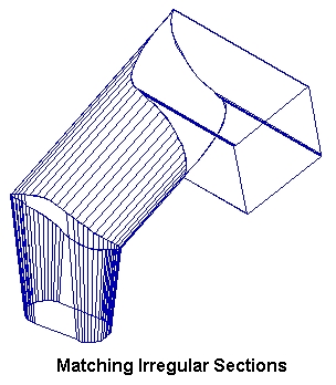
In the case of bends formed between irregular objects, the situation becomes a little more complicated. Any draftsman familiar with the drawing techniques used to intersect pipes and cones will know of the "common central sphere" technique. This technique in effect makes use of the regularity of the pipe or cone as is in fact used in the system to achieve a straight cut for inline intersection (see later). An irregular bend will not usually conform to such criteria.
Consider a bend formed between oblique cones with their oblique offsets in different planes. Or the formation of a bend between an oblique cone and a rectangular tapered duct. In these cases, the common central sphere technique would not suffice. SHEET LIGHTNING takes care of the operation but there are various options available which alter the way in which the objects are matched.
These options fall into two categories:
 The
position of the C/Ls of the objects must be adjusted in some way to place
them in a central position relative to each other to form an exact fit.
For irregular objects, this will often mean that their centre lines do
not in fact meet but cross at an offset distance. C/Ls that do meet, will
sometimes have to be parted to form the required bend.The
dimensions of the objects may have to be adjusted to complete the fit so
that in a cut and weld operation both objects are cut off completely.
The
position of the C/Ls of the objects must be adjusted in some way to place
them in a central position relative to each other to form an exact fit.
For irregular objects, this will often mean that their centre lines do
not in fact meet but cross at an offset distance. C/Ls that do meet, will
sometimes have to be parted to form the required bend.The
dimensions of the objects may have to be adjusted to complete the fit so
that in a cut and weld operation both objects are cut off completely.Note that these adjustments are often inter-dependent which means that adjustment of one will necessitate re-adjustment of the other to maintain the fit.
There are alternative methods for achieving both of these requirements that are set using the match menu commands. These are as follows:
- C/L Displacement
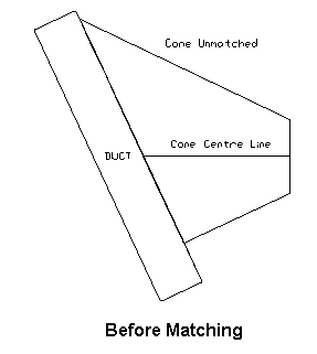
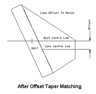
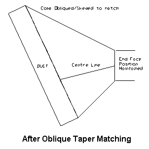
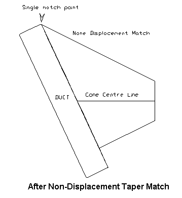
The mode of C/L displacement is controlled by the displace option in the match menu. The examples demonstrate the various settings and their effect on a matching operation. An irregular match between a cone and a duct is used illustrate all cases:
OFFST - The offset option causes any adjustment of the object C/L to move both ends in the same direction by the same amount, thus preserving orientation of the line.
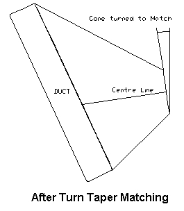
TURN - This option permits adjustment of the C/L position by moving one end only. This in effect pivots the C/L about its other end.
OBLIQ - This option only allows the oblique offset of the related end to be changed with the other end remaining in exactly the same position. The advantage of this is that the opposite end of the object remains exactly as it was before adjustment which is a feature that may be useful when that end of the object is related to another.
ASK - If the toggle is set to ASK, then you will be prompted with a verify box to select which of the options is to be used. The box will appear before each matching operation takes place.
NONE - No displacement of the object is permitted. This feature is intended for use with tees and junctions. Of course, if a bend relationship is to be established, then the objects must be matched. With tees and junctions, that is not always the case, therefore the option is useful when an offset tee is to be formed where only one edge of the tee is matched to the other object. The offset can only be maintained if the C/L centralisation is disabled. In the case of bends, the NONE setting is over-ridden and behaves instead as though the toggle were set to ASK.
- Object Dimension Adjustment
The object dimensions adjustment is controlled by the "Dimension" command in the "Match" menu. There are four settings as follows:
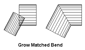
GROW - This option causes the whole of the object to be "grown" in order to achieve a matching size. The grow option is extremely useful to propagate a size adjustment right through a complete design. This will become clearer when the chain matching is described later.
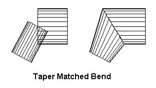
TAPER - The taper adjustment will only allow adjustment of the object dimensions at the related end. Therefore the dimensions of the other end are preserved.
ASK - When the dimension option is set to ask, then a verify box will request which type of matching is to be used before each matching operation is undertaken.
NONE - Prevents any adjustment being made to the object dimensions. This is often used to centralise a tee object to the C/L of a related object without adjusting any dimension. As with the displace option in the case of bends, this setting is over-ridden and causes the operation to behave as if it were set to ASK.
One final point to note when using the dimension option, is that in the case of a rectangular end of an object, any adjustment will always preserve the relative proportions of width and height.
- Tees
The calculation for tee relationships is similar to that of bends but less restrictive. In this case, it is only necessary that the one object is cut off fully by the other rather than for them to cut each other off. The diameter of teeing object therefore has a maximum size but there is no minimum. The teeing object can be smaller than its maximum size and still be cut off. In this respect there is more freedom of choice in the sizing of an object. Despite this, the matching operation always works to the greatest size possible in such a tee. Smaller sizes must be set manually and the matching of these objects should be disabled or refused if the maximum size adjustment is not required.
- Junctions
Junctions are even less restricted and can practically be sized as required. In this case the operation of matching will still fit one size exactly to the other in the same manner as the tee. Differing sizes can be set manually.
- Copy Angle
The copy angle option is an additional feature. With this option enabled, the taper angle of one object can be passed on to another. The default is for the option to be disabled and the taper angle of each object is treated individually. The feature is useful however in such cases as forming a lobster-back bend. A constant angle of taper can be transmitted throughout the bend using a chain matching operation (see later).
- Add Matching
The "Add Matching" command is a toggle which can be set the "On", "Off" or "C/L". When "Add Matching" is enabled, any new object placed in the design will immediately be matched to any related object as soon as it is de-activated by placing the second end in position. By default, this feature is enabled but can be switched off from the match menu. If any of the matching options are set to ASK the relevant verify boxes will appear requesting the type of matching to be employed by the new object.
The third value "C/L" will prevent a new C/L being transformed into the default object when placed in the design. Instead it remains as a C/L and can therefore be used as a dummy line. If a dummy line is to be changed into an object use the "Outline" command in the design menu.
- Chain Matching
Chain matching is a feature which allows a complete design of related objects to be re- matched in one sweep. There are two ways of initiating such an operation.
i.
Chain
matching can also be initiated directly from the match menu. To do this
select the "Initiate" command. The object selector will then be activated
requesting where the matching should be initiated from. Alternatively the
chain match command in the design menu can be used.
- The Chain Matching Process
Once the process of chain matching has been initiated, the effect is as follows:
The
selected object is searched for related objects. These are entered into
a queue and then each one in turn is matched to its source.
ii.As
each of the objects is matched, it too is searched for related objects
which have not already been matched in the current operation. If any are
found, they are entered in the queue and matched in turn.
iii.If
several objects are found to be related and are added into the queue, the
effect is a fanning out along the separate branches as the relationships
are detected and the matching is performed. If the "Match Mode" option
is set to ASK, then by choosing NO at the verify prompt the matching of
the object is prevented and any related objects are not entered in the
queue, thus ending all matching along that particular branch.
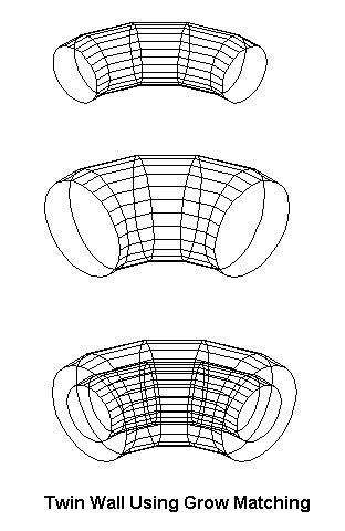
- Twin Wall Using Grow Matching
A useful and powerful facility of creating multiple walled designs is provided by the grow matching operation. A design can be copied to disk, "grown" to ac different overall size and then the original design appended over the top of the resized objects. Make sure however the "Non-Relative" command in the "Efficiency" menu is set to none before cut & welding the design.
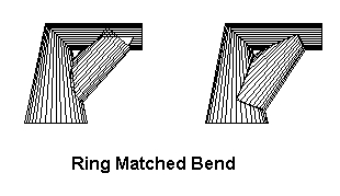
- Ring Matching
When a matching operation is performed, a situation can easily be encountered where the sequence of matching one object to another encounters an object which has already been set or matched in the same operation. Take for example a situation where three pipes are joined together with bend relationships in the form of a triangle. The third pipe will try to continue the chain back to the one that was originally initiated. In other words a "ring" is encountered. In such a case a special kind of matching is available called "Ring Matching" which will adjust both ends of the object to fit their respectively related pre-matched objects. Because this can alter the dimensions of an object completely, the match menu holds an option called "Ring Matching" which can be used to prevent, or cause a verify request before ring matching is permitted.
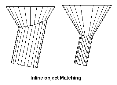
- In-line Objects
The situation is often encountered where objects inter-sect each other in-line or close to in-line with each other. It is clear to see that in this case, irrespective of the type of relationships that exist or the relative sizes of the objects, they will always cut each other off completely. In such cases the objects are copy matched where the dimensions of the related faces are set equal.
In the in-line situation, another problem arises in cases where the two objects are not in any way related. The problem is that the cut can be made in two different ways. The portions of the objects that are cut away and the portions which are left can be reversed to give an equally satisfactory intersection. SHEET LIGHTNING uses simple criteria to decide which ends of the object should in fact be cut away and which should be left.
The criteria depends entirely on the relative positions of the C/Ls as follows:
The
two C/Ls are projected onto a single line at half their relative angle.The
midway point of each projected C/L is taken. The relative position of these
two points decides which end of the object is cut away. The end of the
object nearest to its projected midway point is kept. The other end is
cut away.A few experiments are recommended here in taking the examples given in the figures, moving their relative positions and performing a cut and weld operation. This can be done easily using the "dragging" facility described in sec. 7.3.3.
If a junction relationship is found to exist between two in-line objects, then the same criterion is applied. If on the other hand a relationship exists involving the end of one or both objects such as a tee or bend relationship, then that end will inevitably be the cut away end.
Note that an in-line situation does not necessarily imply that the C/Ls of the objects are exactly in-line. The dimensions of the object can cause an in-line situation to arise even when the objects are at a significant angle. This is detected in a cut and weld operation and the above criterion is applied.
- Common Central Sphere
The common central sphere technique is used in the geometrical drawing procedures. It is used to get a correct match between intersecting right cones. The matching of right cones using the techniques described so far would in fact give exactly the same result, except in the in-line match case. In this case there may be may different sizes that perform a legal match. However if the common central sphere technique is applied to these cases it ensures that the objects are cut by a single cutting plane. In other words in some 3D view of the intersection the cut line is seen to be straight. The C.C.Sphere option in the match menu is therefore provided to deal with these as a special case. If the facility is disabled then normal face matching takes over.
- Copy Matching
When two objects meet approximately in line with each other (two cones for example) it is often possible for them to have a range of relative sizes and still be adequately matched. In this situation normal matching would simply accept whatever sizes already exist. In such a situation it is often required that the faces off the two objects are the same size as each other. To ensure this face matching should be turned on. Whether the object is grown or tapered is determined as with other matching by the setting of the "Dimension" option.
- Individual Matching
The individual matching process is much the same as the add match. The difference is that add matching will automatically match in any new object that is added to the design. Individual matching will allow any individual object already in the design to be matched to its relations. If the conditions exist where the chosen object is related to more than one other then a ring match will be attempted. To perform the operation select "Individual" in the "Match" menu and select the desired object using the object selector. Alternatively use the MATCH1 command in the design menu.