Sheet Lighting (the full version) has two design environments - The Parametric environment and the CAD environment. Or in the case of Sheet Lightning Lite the program has only the Parametric environment.
Parametric Environment
The Parametric environment requires input of typed dimensions values only, and requires no 3D CAD skills
to use it. Sheet Lightning comes with a pre-defined library of parametric template files. Each parametric
template has a unique design complete with a full set of dimensions for defining/redefining it. Generally
the number of objects in the design and the shape of object sections are fixed but everything else is
variable by altering the dimensions in the property editor. This may include object shape dimensions,
lengths and relative orientations.
The parametric library can be browsed (i.e. previewed) using the Design File Browser .
This is an easy to
use visual facility for locating the required design. In addition to the parametric file library Sheet Lightning
also provides special design facilities such as design for Swept Bends (i.e. also known as segmented or
lobster back bends). The special tools are accessed via the 'Tools' menu.
The parametric library includes:
1. Bends
2. Tees
3. Junctions
4. Adapters between - Round, Square, Rectangle, Oval, Rounder Rectangle and other.
5. Diverters.
6. Skewed (oblique) objects (all the above).
7. 'Cornerized' adapters (i.e. maintains straight sides).
8. Unusual and non-standard designs.
CAD Environment
The main limitation of the parametric environment is that it cannot realistically be used for large designs
with many object, or designs of unusual complexity. As the number of objects and the object complexity
increases the number of parameters required to define it tends to escalate. This is especially true when the
objects have orientation in all three spatial dimensions. The solution to this problem is the full 3D CAD
environment (not available in Sheet Lightning Lite). Using this environment objects can be:
1. Created and destroyed
2. Located with 3D orientation (with or without construction lines).
3. Section shapes selected and section dimensions defined.
4. Skewed.
5. Connected (i.e. intersected) as bends, tees or junction.
6. Matched (automatic size adjustments)
7. Copy and pasted together.
8. Duplicated.
9. Modified in all respects.
10. Rotated, scaled.
11. Dismantled and reassembled.
12. Converted to parametric designs.
The last item on the list is the facility through which all parametric designs in the library have been created
and it can be used to extend the design libraries indefinitely. CAD designs can be converted to parametric
designs. This process adds all possible dimensions according to certain rules, and creates a new
parametric design that can be saved to the parametric library. The dimensions that are attached can be
filtered down as required so that only the dimensions that are required are saved and the file does not
contain unnecessary complexity. A parametric design can also at any time be converted back into a CAD
design and returned to a 3D CAD window for modification. The process of conversion is generally very
quick and easy so it is perfectly feasible to work to a large measure in 3D but convert the designs to and
from parametric designs just to enable the alteration of single dimensions (rather than altering it using the
CAD tools). It is also possible to copy part or all of a CAD or parametric design into the clipboard and then
paste into another design, thus appending one design to another.
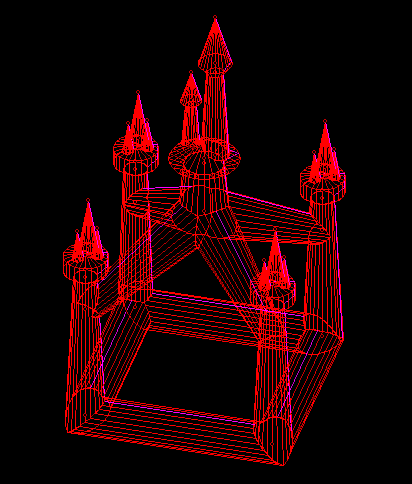
Generally the CAD environment provides unlimited design scope. Sheet Lightning is able to handle designs
with multiple intersecting objects:
Fig: Unlimited Complexity of Design
Common Tools for Both Environments
Both the Parametric and CAD environments provide tools for printing 3D designs and unfolded patterns in
both overall layout or full size patterns. The full size pattern priniting can be spread over as many printer
pages as required, so it is possible to print huge patterns with just a small printer. Printed patterns can
then be used in a manual manufacturing process. The program also includes full DXF output from both
design and parametric environments and the ability to seamlessly export 3D CAD or 2D pattern data to
another application or CAD system. The transfer usually requires no setup at all and is available at the
click of the CAD export button (if a CAD system is installed to receive it). For details see - Exporting Data
to CAD Systems.