The Swept Bend (or Lobster back bend) designer is a special powerful design feature for
designing a segmented bend with any bend angle, number of segments and start and finish
diameters. It is accessed in two possible ways.
First: Using the 'New' command for independent bend creation.
Second: From the Tools menu in the 3D design view where it is able to design a bend directly into
an existing single joint connection between two pipes/cones in the 3D view (these must be
selected in the 3D view for the command to be available). The command the replaces the
connection and the original pipes with the bend segments and the leftovers of the original pipes (if
any).
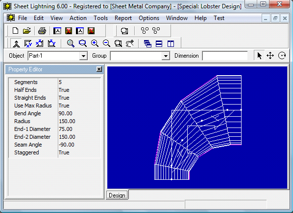
Fig: Special Swept (Lobster) Bend Design Feature
Parameters
Segments: integer - Defines the number of segments in the bend, including the half segments at
each end if it has them.
Half Ends: Boolean - If set to True the bend has half angle segments at each end. If False then
the end pieces are full angle pieces.
Straight Ends: Boolean - If set to True the end pieces of the bend are straight, having no taper.
If set to False the end pieces have the same taper angle as the rest of the bend.
Use Maximum Radius: Boolean - This parameter is does not exist for individual bend design
but when the bend designer is invoked onto a pipe/cone connection in the 3D view then this
parameter allows the bend radius to be set to the maximum radius that can used to replace the
selected pipes/cones. This maximum is determined by the length of the pipes/cones - which will
be fixed by the shortest pipe/cone. If set to False the Radius value is used and it is not changed.
If the radius is less than the maximum possible then there will be leftover pieces for the original
pipes/cones. If set to True and the two pipes/cones are of different length then there will be a
leftover piece for one of the pipes only.
Radius : Value - The radius of the bend from the bend center point to either the start or finish
open end nodes of the bend. If the bend was invoked from the 3D view and the Maximum Radius
parameter is set to True then the Radius parameter will be automatically adjusted and set to the
maximum value.
End-1 Diameter : Value - The start diameter of the bend. If the end diameters are different the
bend will be tapered with conical pieces.
End-2 Diameter : Value - The final diameter of the bend. If the end diameters are different the
bend will be tapered with conical pieces.
Seam Angle : Angle - This defines the position of the seam on all pieces (except if the Staggered parameter is set to True - see next). A value of zero will place the seam on the on the
upper side of the bend (nearest in the XY view). A value of 90 deg will place it on the outside of
the bend. A value of -90 deg will place it on the inside of the bend.
Staggered : Boolean - If set to True then the first bend segment will have the seam positioned
according to the Seam Angle setting, but the next and each alternate piece will have the seam
positioned at 180 deg to the seam angle setting. This allow conservation of material in the flat
patterns because the pieces can be closely nested together.